Introduction
This is a demonstration and experiment kit for PID tuning experiments.
Folder Structure
- circuit: The circuit design
- design
- CAD: SolidWorks 2016 design files
- STL_3dPrint: STL files needed to be printed
- docs: Documentation
- firmware: The firmware of the ESP32 development board
Circuit
Circuit design was done using the software named Fritzing, and the schematic is available in PDF format.

Design
The complete CAD design is available as a SolidWorks 2016 model from here. Additionally, 3d printable parts will be available as STL files from here
Bill of Materials
- ESP32 Dev Board
- TB6612FNG (Motor Driver)
- N20 DC Geared Motor (Recommended Motor: 6v 100rpm)
- 100kOhm Potentiometer
- 5mm Form Board (Size: A4)
- Limit Switches (Optional, previously realized those are not required)
- Vero Board
- Circuit Wire
- A few 3mm screws and nuts
- M3x15 2pcs
- M3x35 1pcs
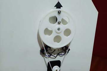
- 3D Printed Components
- Arrow Gear (PLA, White)
- Motor Gear (PLA, White)
- Motor Bracket (PLA, Black)
- Belt (TPU or Flexible Material)
Firmware
The complete firmware is available here. The microcontroller used here is ESP32 Dev Board. But it is possible to change the firmware a little and use it with another microcontroller.
Can change following variables to alter the kP, kI and kD constants.
//PID constants
double kp = 15;
double ki = 0.01;
double kd = 0.05;
You can build and upload the firmware using PlatformIO.
Example

Tags
ESP32
PlatformIO
Firmware